

1000 Series Exit Devices
ANSI Grade 1 Extra Heavy Duty
The Product
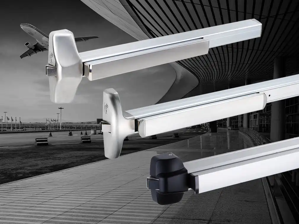
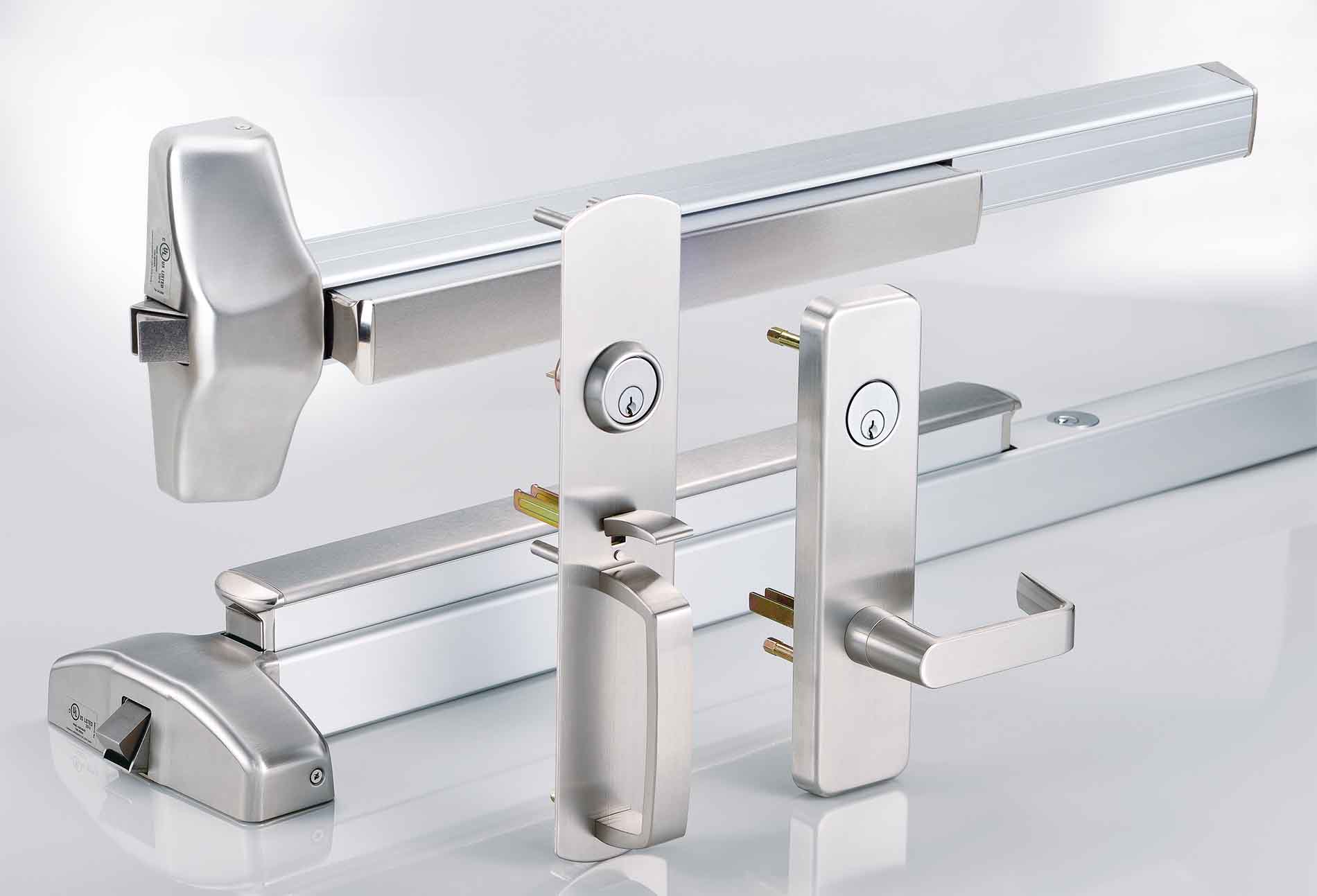
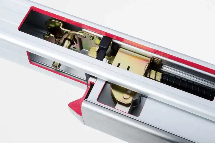
1000 Series Exit Devices and Trims are designed for new or retrofit installation into other manufacturers’ devices. Push Bar assembly’s smooth and reduced projection minimizes catch hazard. Device function is field selectable by adaptation with selected type of trim. A full complement of lever trim is available in wide range of architectural finishes.
The ANSI/BHMA A156.3-2014 Grade 1
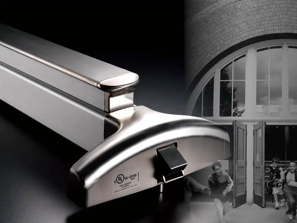
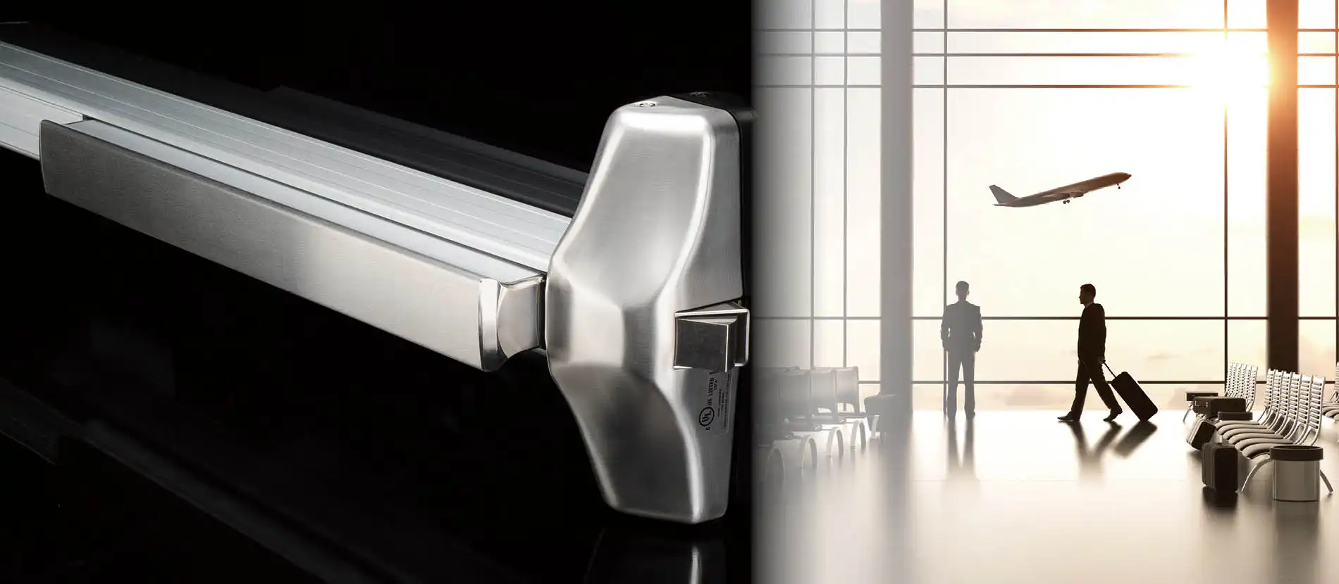
Inherits from the excellent quality and performance of Klacci, the 1000 Series exit device is certified to meet ANSI/UL305 and the ANSI/BHMA A156.3-2014 Grade 1 cycle test requirement. Other than the already rigorous testing standard, the latch needs to withstand a 20 lbs weight loading to it in the cycle test to make sure it stays latched during any viciousness attempts. Devices and trims are also UL/cUL listed for panic hardware or fire-rated hardware. 1000 Series provides superior durability for high impact applications such as offices, schools, banks, assisted living facilities and other institutions or commercial buildings.
A gentle push for more convenient accessibility
Less Than 5 lbs of Push Force to Exit
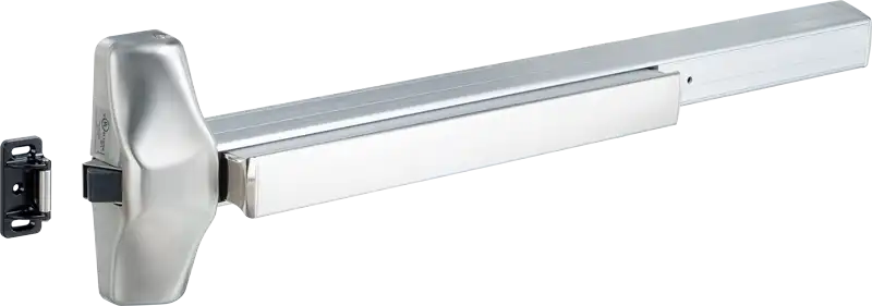
- The push bar requires only 5 lbs, or less of force to retract the latch.
- Operable with one hand without the need of using robust force.
- Meets the 2010 ADA Standards 11B-309.4 and California Building Code 11B-309.4 operation.
- Complies to the new ANSI/BHMA A156.3-2014 Grade 1 cycle test requirement for a net 20 to 22 lbf of load applied on the latch during testing.
- Specify one for all your needs – panic or fire rated doors, high traffic exits, full accessibility areas.
Strength is Not the only Option, Exit Control Can Be Gentle
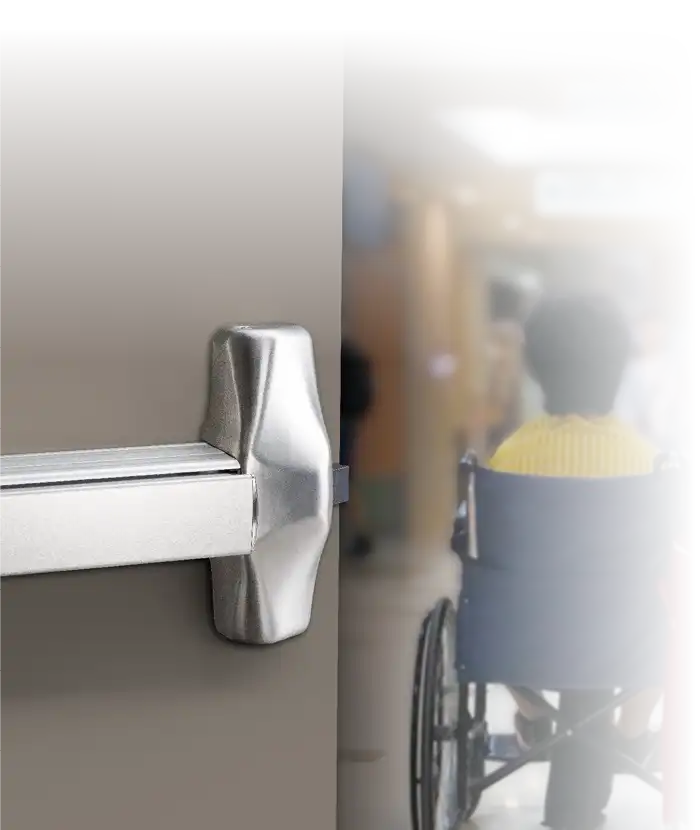
Without compromising any strength and durability of the Klacci 1000 Series exit device, the accessible Rim Exit Device can be operated with 5 lbs of push force. Not only it meets the requirements of the 2010 ADA Standards and California Building Code 11B, the accessible rim exit devices are most suitable for accessibility demand from hospitals or health care centers.
The Exit Device for Anyone, Any Places
The accessible Rim Exit Device makes sure the exit can be operable with the least amount of force, while keeping the maximum strength. No one should be exempted from evacuation when it happens. Simply the choice of safety and security.
From Keyed Access to Smart Access
Sectional Readers for 1000 Series
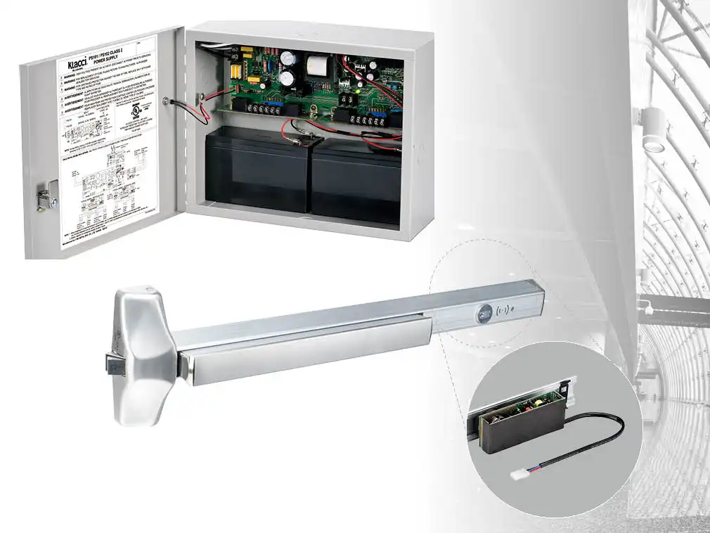
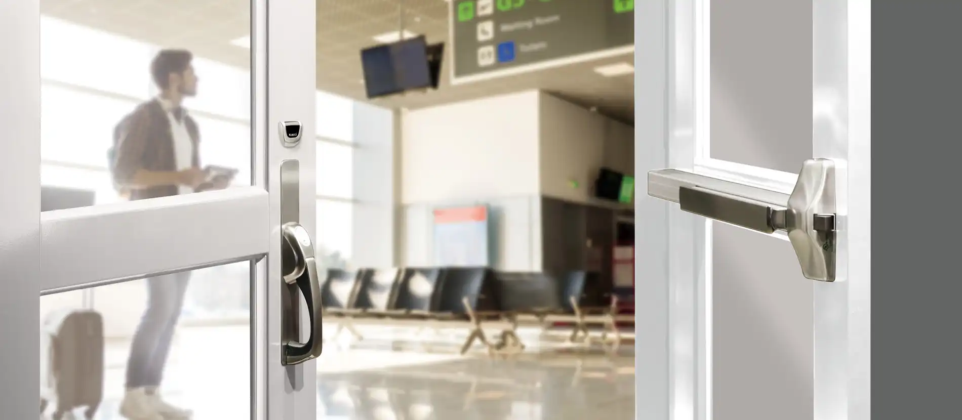
Sectional readers make simple on converting your conventional exit doors into smart electrified access controls. Benefits from the expertise of Klacci, you can control your access by choosing various of methods from passcode entry or RFID card, to mobile phone app unlocking or even using facial recognition.
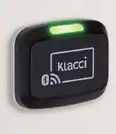 | 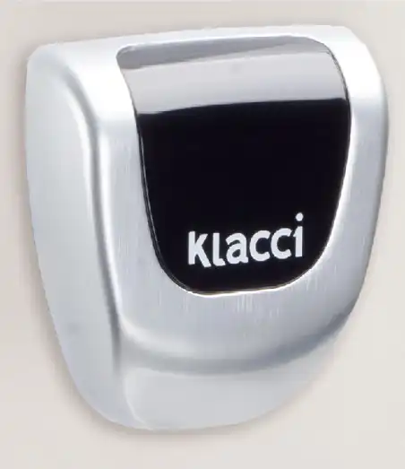 | 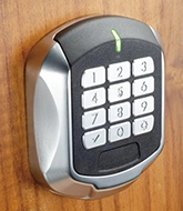 |
| iF+R Series Reader Unlocking method: Passcode + Facial Recognition thru mobile phone app, RFID card | iF-R Series Reader Unlocking method: Passcode + Facial Recognition thru mobile phone app | iK Series Reader Unlocking method: Passcode with physical keypad |
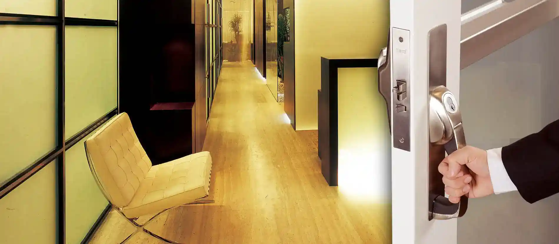
Door Opening with One Pull Motion
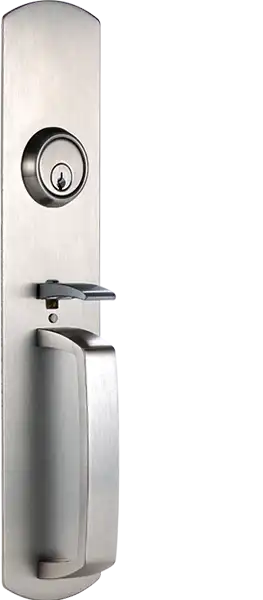
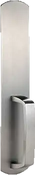
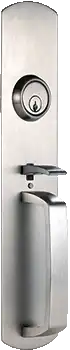
600 Series Pull Handle

- Get a more comfortable grip with its curved design and touch.
- The slanted cylinder design allows face to face sight with the user.
- An ergonomic grip handle that brings balance between functionality and aesthetics.

Security At-a-glance
Classroom Security Solutions
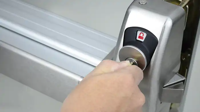
Indicators provide the most direct visual assistance of the locked/unlocked status of the door during emergency events. The indicator window and message is designed to have status of the lock able to be seen clearly distance away within the inside of the room.
Now the 1000 Series Exit Device comes with the available indicator option on double keyed devices. Verifying the locked/unlocked status of critical main entrances or exits can be peace of mind.
When Sequence Orders Matter
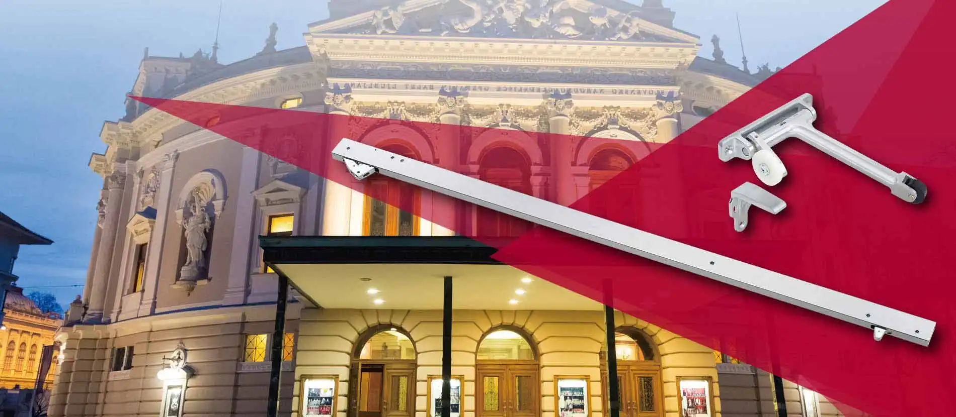
We all know one comes before two in numbers, safety comes ahead of convenience. Klacci’s CR Series Bar Coordinators offer a simple yet effective way of regulating double door entries. These products guarantee a correct order of door closing and prevent that any entry that is not properly closed may cause a safety concern in case of emergency.
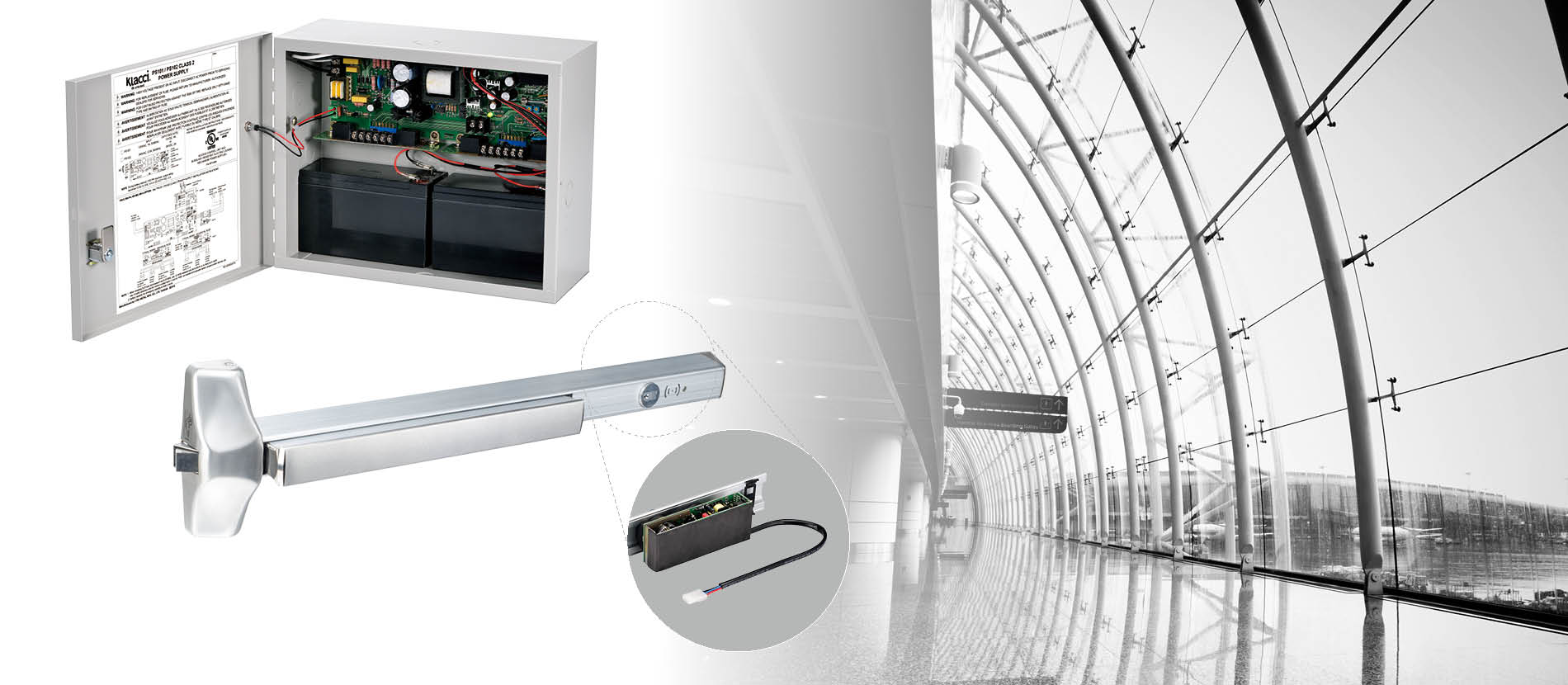
Electrical Exit Devices
Features
The 1000 Series Exit Devices are fabricated and blended with simplicity, strength, durability, aesthetics and installer-friendly innovations.
- Devices and trims are designed for new or retrofit installation into other manufacturers’ exit devices and trims.
- Made to comply with the highest safety and security standards in industry.
- UL/cUL listed for panic hardware or 3-hour Fire Rated Exit Hardware.
- Certified to ANSI/UL305 and ANSI/BHMA A156.3-2014 Grade 1.
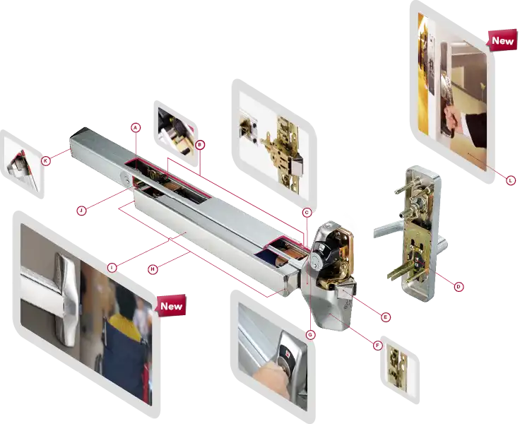
Simple cylinder built in add-on kit.
Special plastic inserts and rubber bumpers reduce noise and don’t fail under high or low temperatures. Impervious to petroleum lubricants.
Detachable center case allows switching between mechanical and electrical options which replaces the need of buying two complete sets.
Replaceable cam breaks at a predetermined load to prevent further damage of the trim mechanism. Handing change is simple and easy, just remove screw and cam from mechanism and rotate lever to desired position, then replace cam and fasten the screw.
Stainless steel latch and deadlatching blade add perceived value.
Center case with maximum versatility, Surface and concealed vertical rods can be adjusted inside the center case with an ingenious rod holder design.
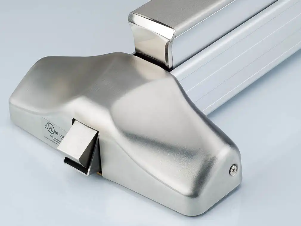
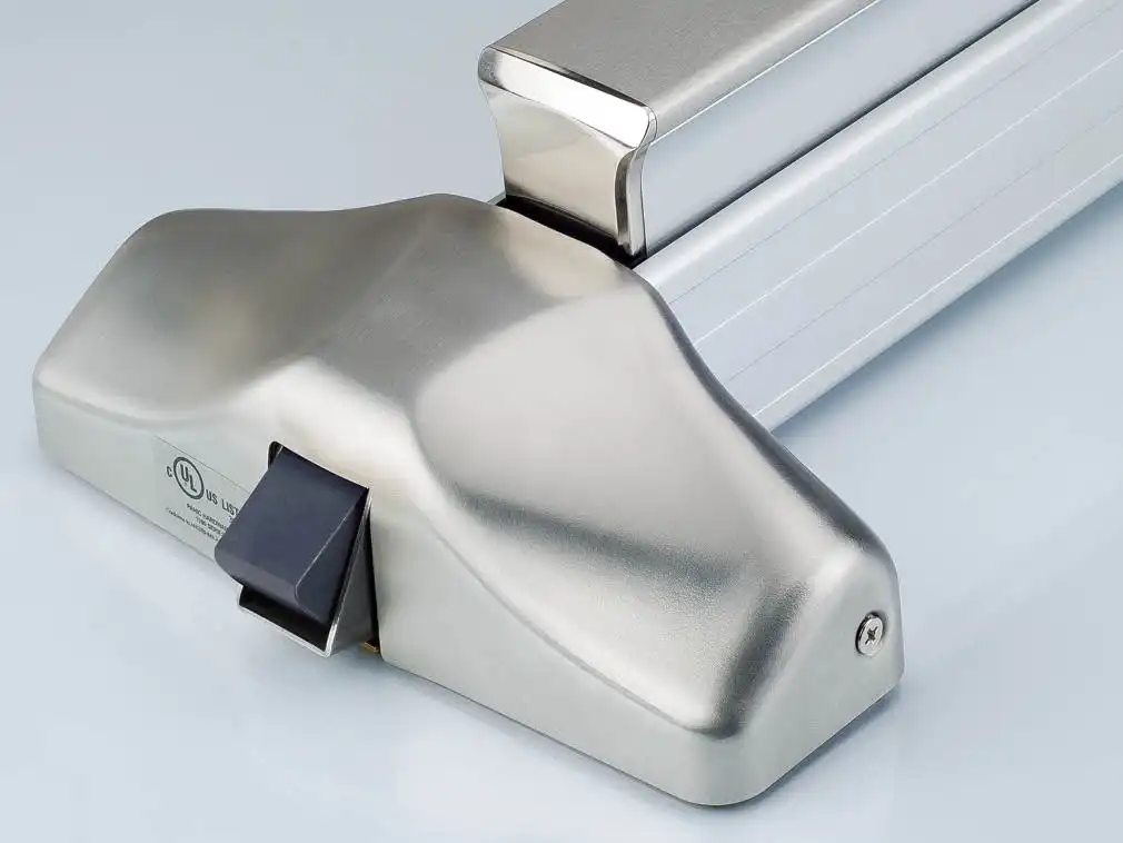
Double cylinder with indicator devices are used as classroom intruder locks, allowing the locking of the outside trim without opening the door.
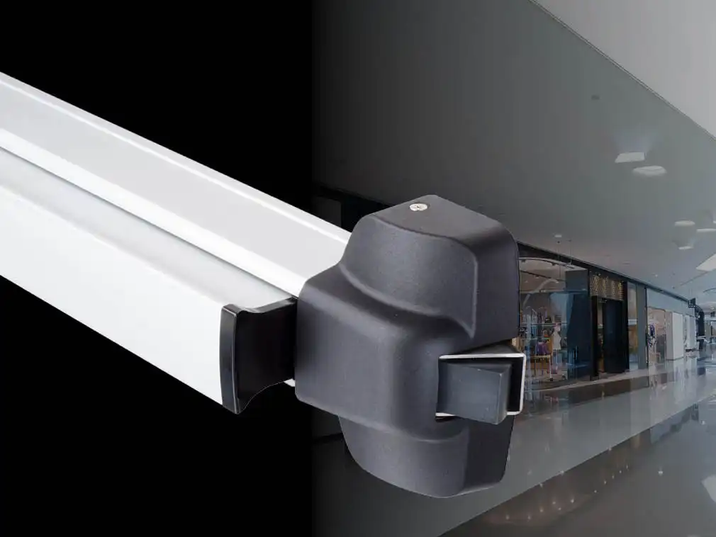
Integrated end cap reduced projection minimizes catch hazard and add stability to the push bar to move smoothly regardless of where the pressure is applied on push bar.
Push bar is smoothly surfaced. Light force applied to the push bar can release the latch. Accessible version is also available to meet the 2010 ADA Standards and Accessible Design to operate the device with 5 lbs of force.
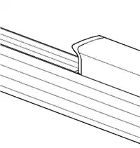
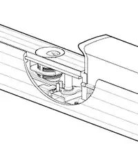
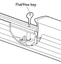
Dogging can be done with an allen wrench, a small flat key or a flat blade screwdriver.
Flush end cap design.
Option of 600 Series Pull Handle trim – new experience of door opening with no other products in the market can match.
Device Options
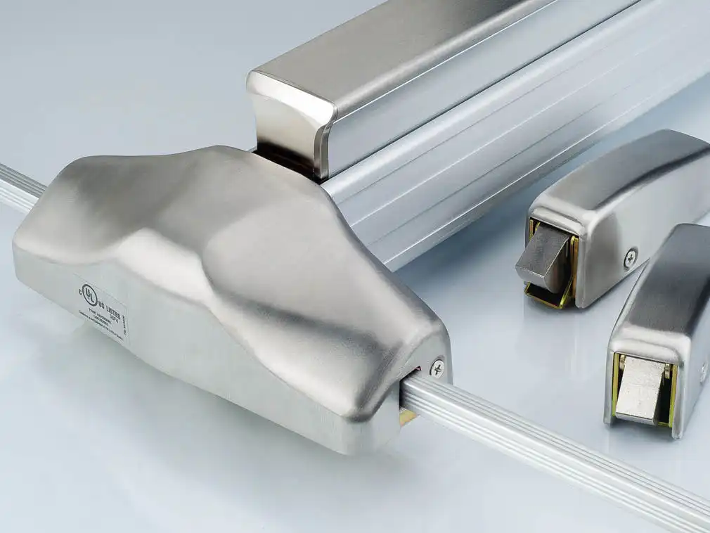
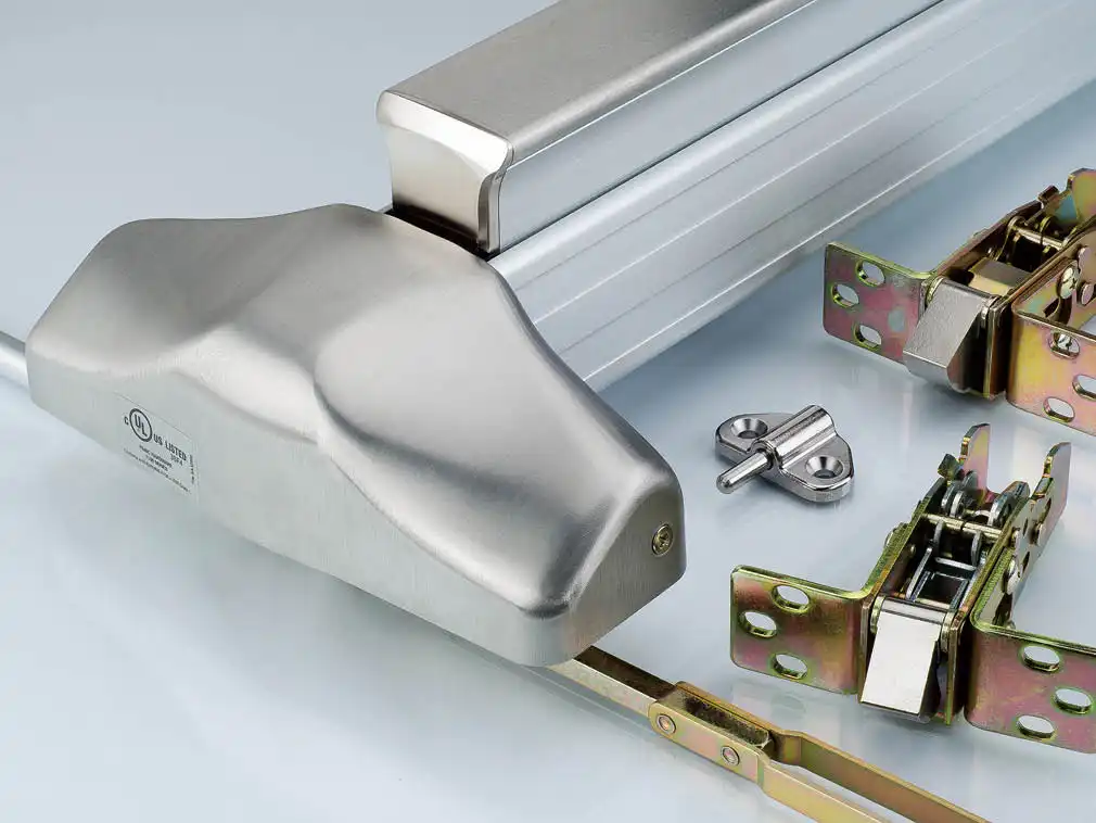
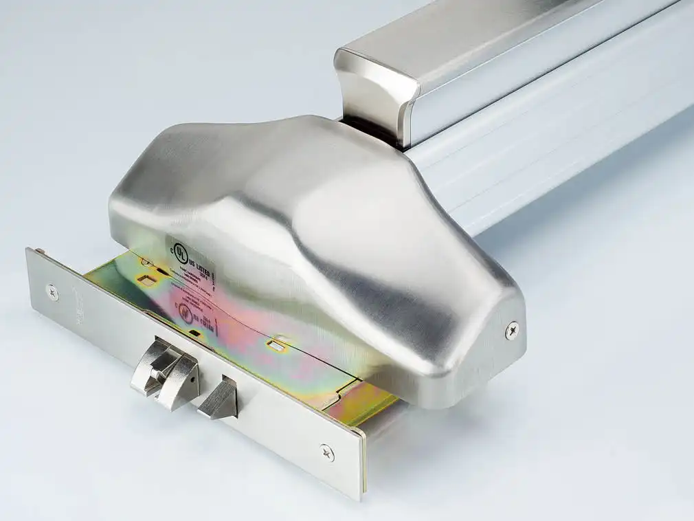
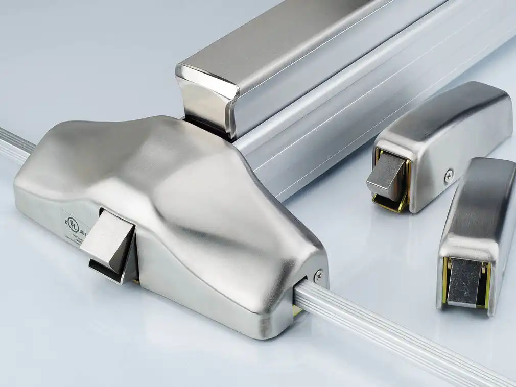
Details
General Overview
Device Material
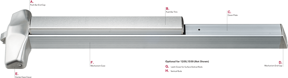
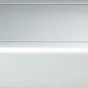
1000 Series is furnished standard with grooved case. Smooth surface style is available. The two styles are mechanically and dimensionally identical and come with a wide selection of finishes.
Finishes
 | ||||||
| Color | ANSI/BHMA | US | B.E.G. | A.D. | C.F.H. | |
 | Polished Brass | 605 | 3 | Brass, Polished | Plated | Buffed Anodized |
 | Satin Brass | 606 | 4 | Brass, Satin | Plated | Anodized |
 | Polished Bronze | 611 | 9 | Bronze, Polished | Plated | Buffed Anodized |
 | Satin Bronze | 612 | 10 | Bronze, Satin | Plated | Anodized |
 | Dark Oxidized Satin Bronze | 613 | 10B | Bronze, Satin; Dark Oxidized | Plated | Anodized |
 | Polished Chrome | 625 | 26 | Brass, Polished & Plated | Plated | Buffed Anodized |
 | Satin Chrome | 626 | 26D | Brass, Satin & Plated | Plated | Anodized |
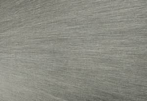 | Satin Stainless Steel | 630 | 32D | St. Steel, Satin | Plated | Anodized |
Push Bar Trim Options
- Embossed “PUSH”
- Braille, embossed “CAUTION STAIRWELL”
- Red silk screen lettered “EMERGENCY EXIT ONLY – PUSH TO OPEN & SOUND ALARM”
Mechanism Case Options
 Smooth | 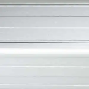 Grooved |
Functions
| ANSI/ BHMA | Operation | Trim Option | ||
| 200 Series Thumbpiece | 300 Series Escutcheon | 600 Series Pull Handle | ||
| 01 | Exit Only | 201 | N | N |
| 02 | Dummy Pull Only | 202 | 302 | 602 |
| 03 | Night Latch, Key Retracts Latchbolt | 203R/203M | N | N |
| 05 | Key Locks or Unlocks Latchbolt | 205R/205M | N | N |
| 07 | Inside / Outside Key Locks or Unlocks Latchbolt (Double Cylinder) | 205M | N | N |
| 08 | Key Locks or Unlocks Latchbolt | N | 308R/308M C308R/C308M | 608R/608M |
| 09 | Night Latch, Key Retracts Latchbolt | N | 309R/309M | 609R/609M |
| 10 | Inside / Outside Key Locks or Unlocks Latchbolt (Double Cylinder) | N | 308R/308M C308R/C308M | N |
| 14 | Lever / Knob Always Active, No Cylinder | N | 314R/314M HL400 | 614R/614M |
| 15 | Thumbpiece Always Active, No Cylinder | 215R/215M | N | N |
Notes:
- Device functions are field selectable with the removal of drive screw in back of center case and determined by the type of trim adaption.
- The operation descriptions of the 600 Series trim is reference to the similar ANSI/BHMA function numbers.
Trim Operation Options
 |  |  |
| 200 Series Thumbpiece | 300 Series Escutcheon | 600 Series Pull Handle |
 |  |  |
| Plate | Pull Only | With Cylinder |
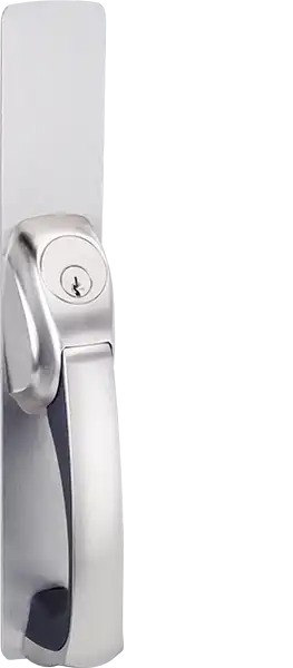
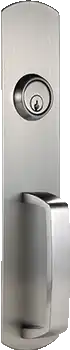
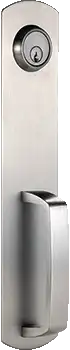
200 Series Thumbpiece
Features
- Trims are furnished with wrought plate and cast solid or forged grips.
- Trims are designed to retrofit into other manufacturers’ devices.
- Trims are UL/cUL certified for ANSI/BHMA A156.3-2014 Grade 1 and 3-hour Fire Rated.
- Trims are through bolted and covering 161 and 86 cutouts. (“GD” grip furnished standard, unless specified).
| ANSI/BHMA | 01 | 02 | 03 | 05 | 05/07* | 15 | |||
|---|---|---|---|---|---|---|---|---|---|
| |  |  |  | |  |  | | |
| Operation | Exit Only | Dummy Pull Only | Night Latch, Key Retracts Latchbolt | Key Locks or Unlocks Latchbolt | Thumbpiece Always Active, No Cylinder | ||||
| Trim No. | 201 | 202 | 203R | 203M | 205R | 205M | 215R | 215M | |
| Device No. | 1100 | 1100 | 1100 | 1100 | 1100 | 1100 | |||
| 1105 | 1105 | 1105 | 1105 | 1105 | 1105 | ||||
| 1200 | 1200 | 1200 | 1200 | 1200 | 1200 | ||||
| 1300 | 1300 | 1300 | 1300 | 1300 | 1300 | ||||
| 1400 | 1400 | 1400 | 1400 | 1400 | 1400 | ||||
| 1500 | 1500 | 1500 | 1500 | 1500 | 1500 | ||||
| Cylinder Type | RIM | Mortise | RIM/Mortise | RIM | Mortise | ||||
Lever / Grip Options
| Grip Options | |
|---|---|
 |  |
| GD type (Standard) | GK type |
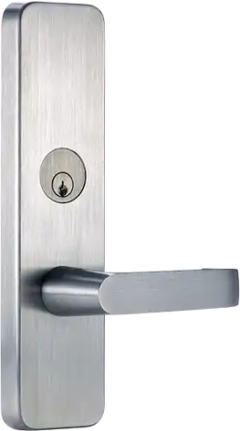
300 Series Escutcheon
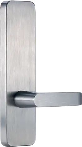 | 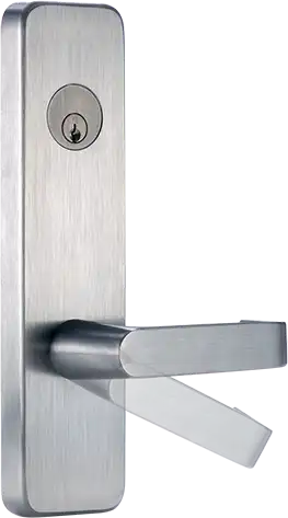 | 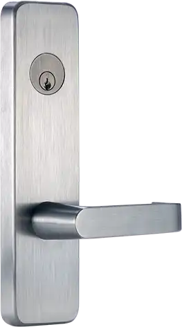 |
| Dummy Trim | Blank Escutcheon | Night Latch |
| Lever or knob rigid for pull operation (For 02 function) | Lever or knob always active (For 14 function) | Key retracts latchbolt. Lever or knob is rigid (For 09 function) |
Features
- Escutcheon and lever with sleek and seamless design produced by casting or forging.
- Trims are designed to retrofit into other manufacturers’ devices.
- Trims are through bolted and covering 161 and 86 cutouts.
- Handing field reversible.
- Trims are UL/cUL certified for ANSI/BHMA A156.3-2014 Grade 1 and 3-hour Fire Rated.
- Specify lever or knob design. (“D” lever furnished standard, unless specified).
| ANSI/BHMA | 02 | 08/10* | 09 | 14 | ||||
|---|---|---|---|---|---|---|---|---|
| | | | | | | 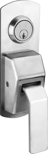 | |
| Operation | Dummy Pull Only | Key Locks or Unlocks Latchbolt | Night Latch, Key Retracts Latchbolt | Lever / Knob Always Active, No Cylinder | Pull latch | |||
| Trim No. | 302 | 308R/C308R | 308M/C308M | 309R | 309 | 314R | 314M | Type “HL 400” |
| Device No. | 1100 | 1100 | 1100 | 1100 | ||||
| 1105 | 1105 | 1105 | 1105 | |||||
| 1200 | 1200 | 1200 | 1200 | |||||
| 1300 | 1300 | 1300 | 1300 | |||||
| 1400 | 1400 | 1400 | 1400 | 1400 | ||||
| 1500 | 1500 | 1500 | 1500 | |||||
| Cylinder Type | Mortise | Mortise | RIM | Mortise | Mortise | |||
Lever / Grip Options
| Lever Options | |||
|---|---|---|---|
 |  |  |  |
| D type (Standard) | Q type | A type | K type |
| Knob Options | ||
|---|---|---|
 |  |  |
| B type (Standard) | P type | T type |
Standard Operation
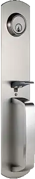
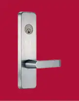 Model 308 Key Locks or Unlocks Lever or Knob (For 08/10 functions) | 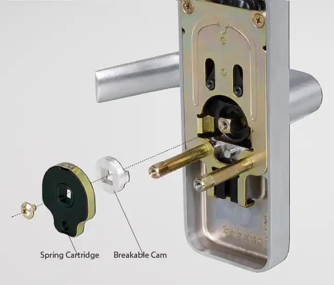 Model 308 trim is composed of heavy duty investment cast steel. An internal breakable cam breaks away when a predetermined load is applied to the outside lever handle in locked mode without damaging the trim or compromising security. The cam is easily replaceable with minimum efforts. The spring cassette and the breakable cam are replaceable parts. |
Clutch Operation
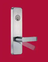 Model C308 Key Locks or Unlocks Lever or Knob (For 08/10 functions) | 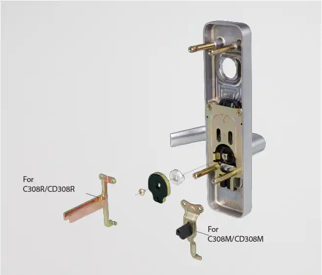 Model C308 Trim is designed to withstand abusive conditions. Working parts are made of heavy duty investment steel. When locked, the lever handle will turn freely and disengage from the center case of the exit device. When an excessive force is applied on the lever handle, it will cause the breakable cam inside the trim to break at a predetermined load, protecting the trim from further damage. The spring cassette and the breakable cam are replaceable parts. Handing Adjust direction of spring cassette and lever handle to switch handing. Trim: can switch between Rim (CD308R) and Mortise (CD308M) functions by changing the lift arm. The lift arm CD308M allows a small range of adjustment, making it easier for installation especially when it comes to dimension differences in door preparation. 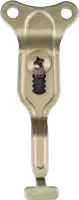 |
 | |
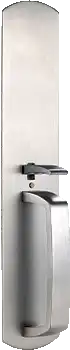
| Pull Only | With Cylinder |
600 Series Pull Handle
Features
- For application with existing Klacci 1000 Series Exit Devices.
- Ease of installation. Same mounting screw hole positions designed to fit Klacci 1000 Series Exit Devices.
- Non-handed.
| ANSI/BHMA | 02 | 08 | 09 | 14 | |||
|---|---|---|---|---|---|---|---|
| | | | ||||
| Operation | Dummy Pull Only | Key Locks or Unlocks Latchbolt | Night Latch, Key Retracts Latchbolt | Pull Handle Always Active, No Cylinder | |||
| Trim No. | 602 | 608R | 608M | 609R | 609M | 614R | 614M |
| Device No. | 1100 | 1100 | 1100 | 1100 | |||
| 1105 | 1105 | 1105 | 1105 | ||||
| 1200 | 1200 | 1200 | 1200 | ||||
| 1300 | 1300 | 1300 | 1300 | ||||
| 1400 | 1400 | 1400 | 1400 | 1400 | |||
| 1500 | 1500 | 1500 | 1500 | ||||
| Cylinder Type | Mortise | Mortise | Mortise | ||||
Specifications
| 1105 | 1100 | 1400 | 1200 | 1300 | 1500 | ||
|---|---|---|---|---|---|---|---|
| Applications | Offices, schools, banks, assisted living facilities and other institutions or commercial buildings. | ||||||
| Certification / Compliance | Panic devices UL/cUL listed for UL305 and ANSI/BHMA A156.3-2014 Grade 1 Panic Hardware. UL/cUL Fire rated for 3-hour Fire Exit Hardware, conforms to UL10C and UBC7-2. Also complies with NFPA 80 Fire doors and windows. Exit devices, levers, trims and pulls comply with American Disability Act (ADA) and NFPA 101 life safety code. | ||||||
| Doors & Preparations | For new or retrofit installation into other manufacturers’ devices. For maximum door opening applications and listings for fire exit devices. | ||||||
| – Mullion | with/without | with/without | |||||
| – Door Thickness | 1-3/4″ (45mm) ~ 2-1/4″ (57mm). Consult factory for other door thickness. | ||||||
| – Door Wide | 3′ (914mm)(standard) ~ 4′ (1219mm). | ||||||
| – Door High | (Panic) | 7′ (2134mm)(standard) ~ 10′ (3048mm). | |||||
| (Fire) | 7′ (2134mm) (standard) ~ 8′ (2438mm). | 7′ (2134mm) (standard) ~ 10′ (3048mm). | 7′ (2134mm) (standard) ~ 8′ (2438mm). | ||||
| – Device Centerline from Finished Floor | 39-5/8″ (1006mm). | ||||||
| – Door Undercut | 1/4″ (6mm). | ||||||
| Center Case | Universal center case, heavy wrought steel and sintered metal parts. Device functions are determined by adaptation with type of trim. | Latch bolt of mortise case can be adjusted for full retraction by Adjustment Finger with fine tuning of adjustment screw in center case. | Heavy wrought steel assembly with top and bottom rod adjustors. Adjustment accessible through center case after installation. | ||||
| Top & Bottom Latch Case | 4-1/2″ × 2-1/8″ × 1-1/2″ (114mm × 54mm × 38mm). | ||||||
| Center Case Latchbolt | Stainless Steel, deadlocking, 3/4″ (19mm) throw. | Stainless Steel, deadlocking, 3/4″ (19mm) throw. | |||||
| Top Latchbolt | Stainless steel, Pullman type deadlocking, 5/8″ (16mm) throw. | ||||||
| Bottom Latchbolt | Stainless steel, Pullman type deadlocking, independent action 5/8″ (16mm) throw. Round slide bolt optional. | ||||||
| Fire Bolt | Available for door openings up to 8′ (2438mm) wide × 10′ (3048mm) high. Specify suffix “LBR”. | ||||||
| Electrical Functions | Can be interfaced with building security systems: | ||||||
| – AL Alarm Exit | √ | √ | √ | √ | √ | √ | |
| – DE Delayed Egress Device | √ | √ | √ | √ | √ | ||
| – ELR Electric Latch Retraction | √ | √ | √ | √ | √ | ||
| – LM Latchbolt Monitoring | √ | √ | √ | √ | √ | ||
| – RX Request to Exit | √ | √ | √ | √ | √ | √ | |
| – SS Signal Switch | √ | √ | √ | √ | √ | ||
| – E Electric Mortise Lock | √ | ||||||
| Dogging | NOT available on fire exit hardware. Flat/hex key dogging standard. Dogging options available for LD, CD, ED (ELR). | ||||||
| Strikes | |||||||
| – Panic | |||||||
| — Top | 106 (roller type) | 216 | 106 (roller type) | ||||
| — Middle | 106Z (roller type) | 106 (roller type) | 306 | 106 (roller type) | |||
| — Bottom | 227 | 227 | 227 | ||||
| – Fire | |||||||
| — Top | 108 (roller type) | 216 | 108 (roller type) | ||||
| — Middle | 108 (roller type) | 108 (roller type) | 306 | 108 (roller type) | |||
| — Bottom | 227F | 227F | 227F | ||||
| Cylinders | NOT furnished standard, specify when required. | ||||||
| Trim | The device and trim are sold separately, easy to mix and match. | ||||||
| Handing | Trim field reversible. Device non-handed. Except for double cylinder option. For double cylinder, specify handing when required. | ||||||
| Fasteners | Machine screws and wood screws are furnished standard. | ||||||
| Sex Bolts (SNB) | Required when used with wood, composite or non-reinforced hollow metal doors. | ||||||
Strikes
Rim Device
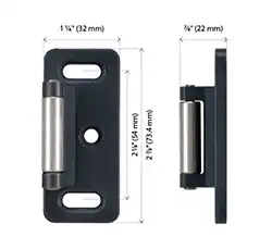 | 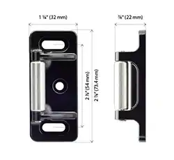 | 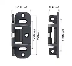 | 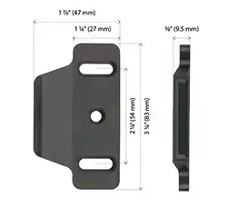 |
| P/N. 106 Rim Strike | P/N. 106Z Rim Strike | P/N. 108 Rim Strike | P/N. 136 Rim Strike |
| For RIM / SVR / 3PT top strike | For RIM / SVR / 3PT top strike | For RIM / SVR / 3PT top strike For double door RIM / 3PT use with F170/F270 mullion | For double door RIM / SVR / CVR combination with coordinator |
  | |  |
Vertical Rod (VR) Device
Top Strike
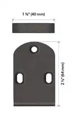 | 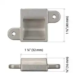 |
| P/N. 215 Top Strike | P/N. 216 Top Strike |
| For flush transom SVR / 3PT | For CVR |
|
Flat Bottom Strike
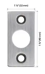 | 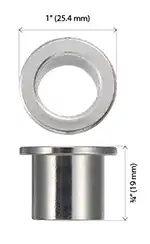 |
| P/N. 225 Flat Bottom Strike | P/N. 226 Flat Bottom Strike |
| Optional for SVR / CVR / 3PT round slide bolt | Optional for SVR / CVR / 3PT round slide bolt |
 | |
Bottom Strike
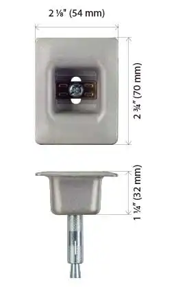 | 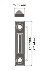 |
| P/N. 227F Bottom Strike | P/N. 224 Bottom Strike |
| Furnished standard for SVR / CVR / 3PT | Optional for SVR / 3PT |
| |
Mortise Device
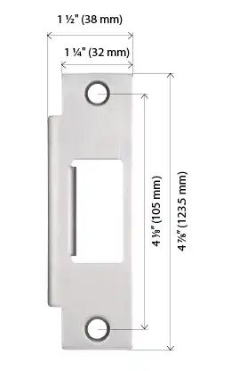 | 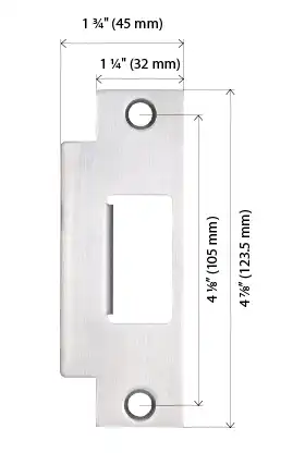 | 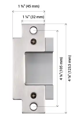 | 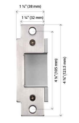 |
| P/N. 336 Strike | P/N. 306 Strike | P/N. 337 Open Back Strike | P/N. 338 Open Back Strike |
| For use on 1-3/4″ (45mm) thick double door with coordinator and astragal. | Furnished standard for use on 1-3/4″ (45mm) or 2-1/4″ (57mm) single door and 2-1/4″ (57mm) double door with coordinator. | For 2-1/4″ (57mm) thick double doors without coordinator. | Furnished standard for 1-3/4″ (45mm) thick double doors without coordinator. |
| | |   |
Shim
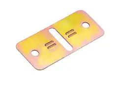 | 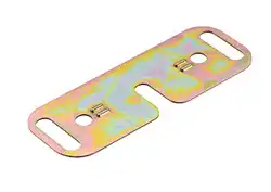 | 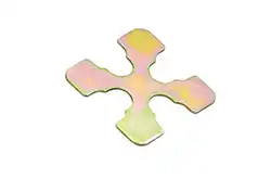 |
| P/N. 616819-010 | P/N. 616819-030 | P/N. 616819-050 |
| For 106 Rim Strike Two (2) pieces furnished standard | For 108 Rim Strike Two (2) pieces furnished standard | For CVR top & bottom latches Strike Sixteen (16) pieces furnished standard for Top and Bottom latches. Eight (8) pieces furnished standard for LBR |
| ANSI Grade 1 | | Panic Application |
| ANSI Grade 2 | | Fire Application |
Double Cylinder with indicator – Handed
| 1100/1105 Rim Device – Handed | 1400 Mortise Device – Handed |
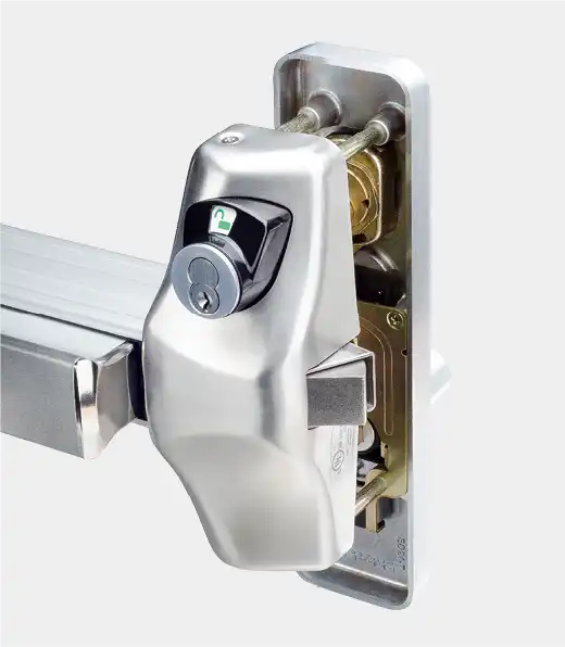 | 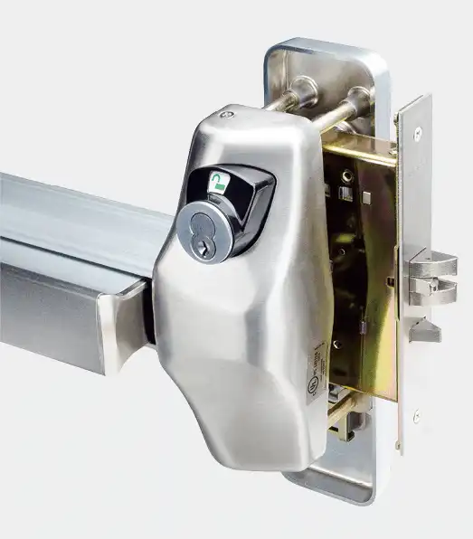 |
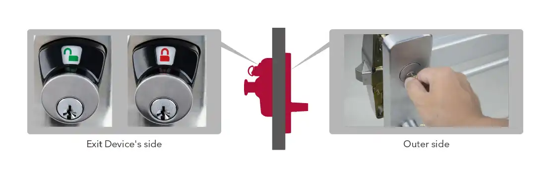
The Double Cylinder option is available on the Rim and Mortise Exit Devices. An indicator device installed on the inner side of door informs whether the outside trim is in a locked or unlocked state.
The outside key cylinder locks or unlocks the outside Trim. Specify Outside Trim with “07” or “10” function depending on trim options. When only the inside key cylinder is required to lock or unlock the outside trim and no outside cylinder operation is necessary for Rim Exit Device specify “08” (outside trim will be with blank mortise cylinder). For Mortise Exit Device specify “14” or “15” function depending on trim options.
Applications
| Device | Cylinder | Trim | ||||||
| Outside Cylinder | Inside Cylinder | Escutcheon | Thumbpiece | |||||
| Cylinder | Cyl. Length (Part/No.) | Door Thickness | Cylinder Cam | Cylinder | Thumbturn | |||
| RIM 1100/1105 | Standard | 1-1/4″ (441-103) & 4240-0202 | 1-3/4″~2″ (45~50mm) | 440-0710 | Rim Cylinder (I/C / STD) Tailpiece Length 3-1/8″ (79.6mm) | OK | 308R / C308 | N/A |
| I/C | 1-3/8″ (442-701) & 4240-0202 | 1-3/4″~2″ (45~50mm) | 440-0711 | |||||
| Mortise 1400 | Standard | 1-1/2″ (441-105) | 1-3/4″~2″ (45~50mm) | 440-0702 | 308M | 205M / 215M | ||
| 1-5/8″ (441-106) | 2″~2-1/4″ (50~57mm) | |||||||
| I/C | 1-1/2″ (442-702) | 1-3/4″~1-7/8″ (45~48mm) | 440-0718 | |||||
| 1-5/8″ (442-703) | 1-7/8″~2-1/8″ (48~54mm) | |||||||
| 1-3/4″ (442-704) | 2-1/8″~2-1/4″ (54~57mm) | |||||||
Cylinder Cam
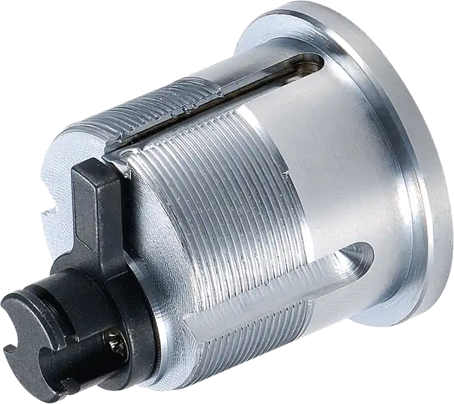 | Extension Cam for RIM Device Double Cylinder (10 function). |
| Illustration | 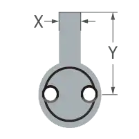 | 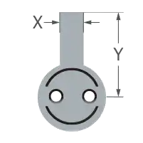 |
| Dimension | X=3/16″ (5mm) Y=3/4″ (19mm) | X=3/16″ (5mm) Y=3/4″ (19mm) |
| Cam No. | 440-0710 | 440-0711 |
Options
Options of keyed cylinder or thumbturn indicator unit
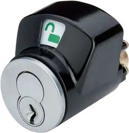 | 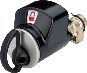 |
| Cylinder | Thumbturn |
Handing of doors
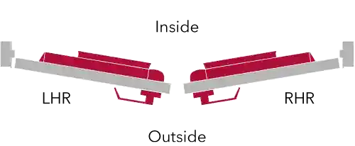
Cylinders
Cylinders are not furnished standard with the device or trim, specify when required. Schlage® C keyway, 6-pin standard, available in 630 or 626 finish. Small format Interchangeable core combinated/uncombinated also available. Specify type and finish when ordering.
Applications
| Cylinder Type | Applications | Trim | Cylinder | Cyl. Length (Part/No.) | Cylinder Cam | |
|---|---|---|---|---|---|---|
Mortise Cylinder I/C |  Standard | 03* / 05* / 07* for Mortise Device | 200 | Standard | 1-3/8″ (441-104) | 440-0702 |
| 08 for RIM/SVR/CVR*/3PT | I/C | 1-3/8″ (442-701) | 440-0718 | |||
| 08 / 09 for Mortise Device | 300 | Standard | 1-1/8″ (441-102) | 440-0704 | ||
| I/C | 1-3/8″ (442-701) | 440-0708 | ||||
| 08 / 09 for Mortise Device | Standard | 1-5/8″ (441-106) | 440-0702 | |||
| I/C | See note 1 | 440-0718 | ||||
| 08 for All Devices | 600** | Standard | 1-1/8″ (441-102) | 440-0714 | ||
| I/C | 1-3/8″ (442-701) | 440-0715 | ||||
| 09 for All Devices | Standard | 1-1/8″ (441-102) | 440-0712 | |||
| I/C | 1-3/8″ (442-701) | 440-0713 | ||||
| Cylinder Dogging | All Devic | Standard | 1-1/4″ (441-103) | 440-0702 | ||
| I/C | 1-3/8″ (442-701) | 440-0718 | ||||
Rim Cylinder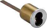 I/C | 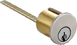 Standard | 03* / 05* for RIM/SVR/CVR/3PT | 200 | Standard I/C | Tailpiece Length 3-1/8″ (79.6mm) | |
| 09 for RIM/SVR/CVR/3PT | 300 | |||||
Cylinder Cam
| Illustration |  | 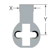 |  |  | 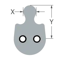 | 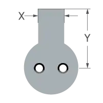 |  |  |
| Dimension | X=1/4″ (6mm) Y=5/8″ (15mm) | X=3/8″ (9.5mm) Y=3/4″ (19mm) | X=5/8″ (16.4mm) Y=9/16″ (13.6mm) | X=3/16″ (4.4mm) Y=7/16″ (11.9mm) | X=1/4″ (6mm) Y=5/8″ (15mm) | X=3/8″ (9.5mm) Y=3/4″ (19mm) | X=5/8″ (16.4mm) Y=9/16″ (13.6mm) | X=3/16″ (4.4mm) Y=7/16″ (11.9mm) |
| Cam No. | 440-0702 | 440-0704 | 440-0712 | 440-0714 | 440-0718 | 440-0708 | 440-0713 | 440-0715 |
Cylinder Guard
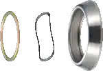 | 4240-0202 / 4240-0203 For use on 203 / 205 / 207 Thumbpiece Trim. CVR with 308R Escutcheon Trim and Mortise with C308R Escutcheon Trim require specialized cylinder guards. 4240-0203 is used for special door thickness applications. For specification details, please contact our sales representative. |
I/C Core
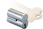 | “A” keyway standard supplied. Specify 6 or 7 pin, combinated or uncombinated and finish 606 or 626 when ordering. Consult factory for other keyways. |
Dogging
 |  |  |  |
| LD | CD | HKD | ED(ELR) |
| Less Dogging | Cylinder Dogging | Flat/Hex Key Dogging | Electrical Dogging |
| Less dogging is available in all 1000 Series panic exit devices. | Available for all models except for fire exit hardware. Cylinder dogging provides the ability to lock down the push bar with a key cylinder, allowing the door to be used in both push/pull mode. To order, specify “CD”. Requires the use of a 1-1/4″ (31.75mm) mortise cylinder (not furnished standard). |
Mullion
| A | B | 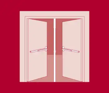 Removable mullions are used with paired doors where a full width opening is only occasionally required. Doors are fitted with Rim exit devices and normally function as single doors. Available in 7′, 8′ or 10′ (2134mm, 2438mm or 3048mm) lengths. |
 |  |
| A | B | |
| Model 170 / F170 Keyed Removable Mullion | Model 270 / F270 Non-Keyed Removable Mullion | |
| Top and Bottom Fittings | Investment cast steel, furnished with steel anchors for floors. | |
| Mullion | 2″ x 3″ (50.8mm x 76.2mm) steel. | |
| Stock size | 8′ (2438mm) length standard, can be cut for opening less than 8′ (2438mm). 10′ (3048mm) length available upon request. | |
| Finishes | 600, 689, 695. | |
| UL Listed | Listed for 3-hour Fire Rated Exit Hardware. | |
| Cylinder | Not furnished standard, keying is standard 1-1/8″ (28.5mm) mortise cylinder with cam. | |
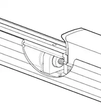
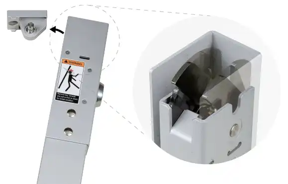
The head design of 170/F170
Miscellaneous
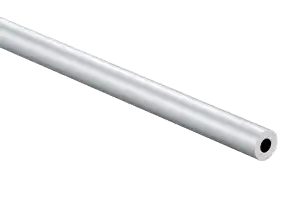
Rod
Top Rod
| Illustration | Device No. | Part No. | Rod Length | For Door Height |
|---|---|---|---|---|
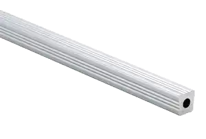 | 1200 1500 (SVR/3PT) | 616823-020 | 36-1/8″ (916mm) | 7′ |
| 616823-030 | 48-1/8″ (1221mm) | 8′ | ||
| 616823-030 Add 616823-040* | 48-1/8″ (1221mm) Add 24″ (609mm) | 10′ | ||
 | 1300 (CVR) | 616823-070 | 37″ (940mm) | 7′ |
| 616823-080 | 49″ (1245mm) | 8′ | ||
| 616823-080 Add 616823-050* | 49″ (1245mm) Add 23-7/8″ (605mm) | 10′ |
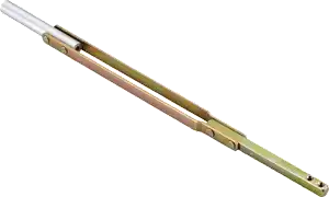
Bottom Rod
For push bar location at 39-5/8″ (1006mm) from finished floor.
| Illustration | Device No. | Part No. | Rod Length |
|---|---|---|---|
| 1200 1500 (SVR/3PT) | 616823-010 | 31-7/8″ (807mm) |
 | 1300 (CVR) | 24682300910 | 34-9/32″ (870mm) |
Dummy Push Bar
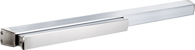
Portable Displaymount
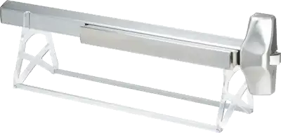
Light Duty Option
PD 420/PD 430
- Size: 24″ × 7-3/8″ × 8″ (600 mm × 190 mm × 205 mm).
- Weight: 1.7 lb (0.8kg).
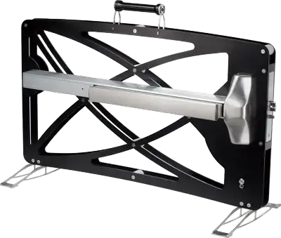
Heavy Duty Option
PD 620/640
- PD 730 for 1200/1500 Surface Vertical Rods.
- PD 750 for 1300 Concealed Vertical Rods.
- Size: 35-1/2″ × 14″ × 28-3/4″ (900mm × 350mm × 730mm).
- Weight: 13 lb (6kg).
PD 730/750
- PD 620 for 1100/1105 Rim exit device.
- PD 640 for 1400 Mortise Lock Exit Devices.
- Size: 35-1/2″ × 14″ × 24-1/2″ (900mm × 350mm × 620mm).
- Weight: 11 lb (5kg).
Note: Size and weight exclude device.
Fire Door – Applications and Listings
F1000 Series Fire Exit Devices Maximum Door Opening Applications and Listings
| Exit Device | Door Material | Single Door | Double Door | ||||
| With 170 mullion | With 270 mullion | VR/VR Same Direction | VR/Mortise Same Direction | VR/VR Double Egress | |||
| F1100 F1105 RIM | Metal | 3 Hours 4′ × 8′ | 3 Hours 8′ × 8′ | 3 Hours 8′ × 8′ | |||
| F1200 SVR | Metal | 3 Hours 4′ x 10′ | 3 Hours 8′ × 10′ | 3 Hours 8′ × 10′ | 3 Hours 8′ × 10′ | ||
| F1200 LBR | Metal | 3 Hours 4′ x 10′ | 3 Hours 8′ × 10′ | 3 Hours 8′ × 10′ | |||
| F1300 CVR | Metal | 3 Hours 4′ x 10′ | 3 Hours 8′ × 10′ | 3 Hours 8′ × 10′ | 3 Hours 8′ × 10′ | ||
| F1300 LBR | Metal | 3 Hours 4′ x 10′ | 3 Hours 8′ × 10′ | 3 Hours 8′ × 10′ | |||
| F1400 Mortise | Metal | 3 Hours 4′ x 10′ | 3 Hours 8′ × 10′ | ||||
| F1500 3PT | Metal | 3 Hours 4′ × 8′ | 3 Hours 8′ × 8′ | 3 Hours 8′ × 8′ | |||
Notes:
- Fire exit device conforms to UL10C and UBC7-2.
- Fire exit device is applicable for wood door with 1-1/2-hour or 1/3-hour fire rating.
- Consult with door manufacturer for specific limitations on fire door assemblies.
Typical Installation
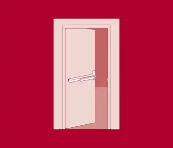
Rim Exit Device / Vertical Rod Exit Devices
| Panic | RIM | 1100 | Up to 4′ × 10′ Door Size |
| 1105 | |||
| SVR | 1200 | ||
| CVR | 1300 | ||
| 3PT | 1500 | ||
| Fire (3 Hours) | RIM | F1100 | Up to 4′ × 8′ Door Size |
| F1105 | |||
| SVR | F1200 | Up to 4′ × 10′ Door Size | |
| CVR | F1300 | ||
| 3PT | F1500 | Up to 4′ × 8′ Door Size |
Mortise Lock Exit Devices
| Panic | Mortise | 1400 | Up to 4′ × 10′ Door Size |
| Fire (3 Hours) | Mortise | F1400 |
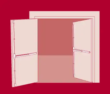
Two Surface Vertical Rod Devices
| Panic | SVR × SVR | 1200 × 1200 | Up to 8′ × 10′ Door Size |
| Fire (3 Hours) | SVR × SVR | F1200 × F1200 |
Two Concealed Vertical Rod Devices
| Panic | CVR × CVR | 1300 × 1300 | Up to 8′ × 10′ Door Size |
| Fire (3 Hours) | CVR × CVR | F1300 × F1300 |
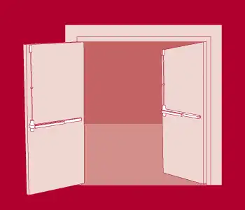
Two Surface Vertical Rod Devices Less Bottom Rod
| Panic | SVR × SVR | 1200LBR × 1200LBR | Up to 8′ × 10′ Door Size |
| Fire (3 Hours) | SVR × SVR | F1200LBR × F1200LBR |
Two Concealed Vertical Rod Devices Less Bottom Rod
| Panic | CVR × CVR | 1300LBR × 1300LBR | Up to 8′ × 10′ Door Size |
| Fire (3 Hours) | CVR × CVR | F1300LBR × F1300LBR |
Two Rim Exit Devices with Removable Mullion
| Panic | RIM × RIM | 1100 × 1100 | Up to 8′ × 10′ Door Size |
| 1105 × 1105 | |||
| Fire (3 Hours) | RIM × RIM | F1100 × F1100 | Up to 8′ × 8′ Door Size |
| F1105 × F1105 |
Two Three-Point Latching Devices with Removable Mullion
| Panic | 3PT × 3PT | 1500 × 1500 | Up to 8′ × 10′ Door Size |
| Fire (3 Hours) | 3PT × 3PT | F1500 × F1500 | Up to 8′ × 8′ Door Size |
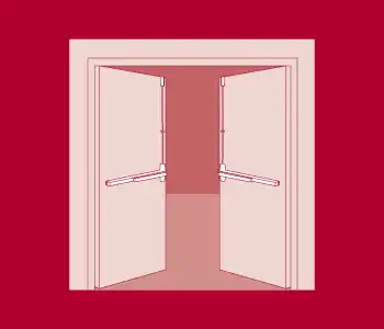
Surface Vertical Rod Devices Less Bottom Rod
| Panic | SVR × SVR | 1200LBR × 1200LBR | Up to 8′ × 10′ Door Size |
| Fire (3 Hours) | SVR × SVR | F1200LBR × F1200LBR |
Concealed Vertical Rod Devices Less Bottom Rod
| Panic | CVR × CVR | 1300LBR × 1300LBR | Up to 8′ × 10′ Door Size |
| Fire (3 Hours) | CVR × CVR | F1300LBR × F1300LBR |
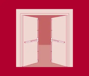
Two Surface Vertical Rod Devices
| Panic | SVR × SVR | 1200 × 1200 | Up to 8′ × 10′ Door Size |
| Fire (3 Hours) | SVR × SVR | F1200 × F1200 |
Two Concealed Vertical Rod Devices
| Panic | CVR × CVR | 1300 × 1300 | Up to 8′ × 10′ Door Size |
| Fire (3 Hours) | CVR × CVR | F1300 × F1300 |
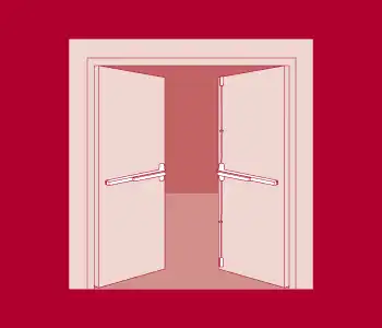
One Rim Exit Device × One Vertical Rod Device
| Panic | RIM × SVR | 1100 × 1200 | Up to 8′ × 10′ Door Size |
| 1105 × 1200 | |||
| RIM × CVR | 1100 × 1300 | ||
| 1105 × 1300 |
One Mortise Lock Exit Device × One Vertical Rod Device
| Panic | Mortise × SVR | 1400 × 1200 | Up to 8′ × 10′ Door Size |
| Mortise × CVR | 1400 × 1300 |